
The Mite
Part :47
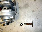 |
Here's the IHI-RHB5 turbo. The hole in the center section is the oil drain hole, the stock oil drain is shown on the far right. I want to use braided stainless for the drain, so I'll have to weld the -8 an fitting onto the flange |
 |
The -8 fitting has been brazed onto the stock IHI flange and now will accept a -8 hose end. |
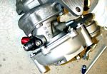 |
Here's the finished and painted fitting on the turbo |
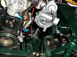 |
And here's the turbo on the car and you can see the oil drain hose coming out of the bottom of the turbo and going to the fitting that I welded onto the oil pan previously |
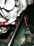 |
Here you can see the oil drain hole, as well as the proximity of the steering shaft to the turbo |
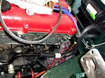 |
I also needed to plumb the heater, and thanks to a Checker auto supply that actually has the heater and radiator hoses on display, I was able to find some hoses that match up exactly to the location I needed! |
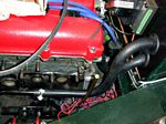 |
Once the hoses were found and attached, I replaced the cover on the heater and re attached the electromotive tec-2 |
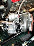 |
I also needed to run water lines to the turbo center section. There were some convenient fittings in the Miata's water neck and return that made the plumbing relatively easy. i drilled and tapped the water neck and water return for 1/4 inch pipe and threaded in pipe-to-dash 8 fittings. I cut apart the stock turbo water inlet pipes, cleaned and painted them and re-attached them in the locations I needed to clear the turbo and the steering shaft. I also ran a teflon-lined -4 hose from the oil feed fitting in the block to the turbo |
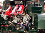 |
Here's the front of the engine |
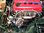 |
And the side, showing the manifold and the oil and water plumbing. That oil line will be clamped down soon |
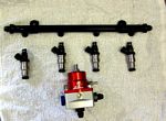 |
Next is the fuel plumbing. I got a set of 6 used injectors from a Toyota Supra Turbo. They are 440 cc/min and low-impedance. I sent them off to RC Engineering and had them cleaned and flowed. They are all just like brand new and flow within a few percent of each other. Also shown is the modified fuel rail and the Aeromotive boost-referenced adjustable fuel pressure regulator. It will keep the fuel pressure at 43 psi regardless of the boost. |
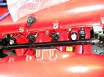 |
Here's the rail and injectors installed |
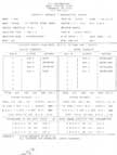 |
This is the pre- and post-cleaning sheet from RC Engineering. It shows the cc per minute flow for each of the injectors before and after cleaning. |
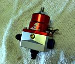 |
The fuel pressure regulator has a nipple fitting for the vacuum/pressure line from the manifold, but I want to use some -4 braided hose, so I'll have to drill and tap the regulator for a pipe thread |
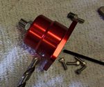 |
I took the top of the regulator and drilled out the threaded hole |
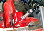 |
Then tapped it 1/8 pipe |
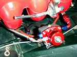 |
And screwed in a 1/8 pipe to -4 fitting and ran a braided line to the manifold to allow the regulator to sense boost, the fuel lines from the fuel rail have also been run to the regulator |
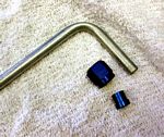 |
I made hard lines to bring the fuel from the pump to the rail and return from the regulator. I bent the lines where needed, then slipped the nut and collar around the tube and then flared the tube with a 37 degree flare tool to allow it to seal to a - fitting |
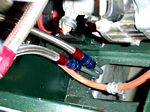 |
Here's the feed and return lines poking up into the engine compartment |
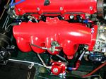 |
And here's the regulator in place |
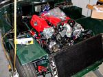 |
And soon, the radiator needs to be plumbed! |
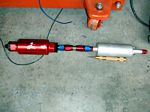 |
This is the Walbro fuel pump and the fuel filter. I connected them with a bit of -6 line to provide some resistance to vibration |
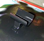 |
I discarded the old fuel pump mount I made and fabbed up a new set for the pump and filter |
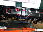 |
Here's the pump and filter zip-tied to the mounts with all the hoses hooked up. I wrapped a bit of radiator hose around the pump and the filter to help with vibration and noise, and on final assembly, they will be hose clamped to the mounts |
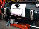 |
Here's what traffic will see.... |
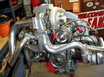 |
And finally, here's a 250 hp, intercooled blow-through turbocharged vw engine That was on a buddy's sandcar. . It's 2275cc and the only VW part on the entire engine is the dipstick. Click the Picture for larger image and build sheet. |