
The Mite
Part 10
Front Suspension, Phase 2
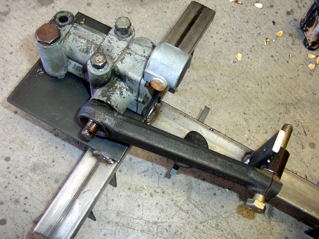 |
Lever shock. On the Sprites and Midgets, it performs both the damping duties and the function of the upper suspension control arm. The shocks on this Sprite are shot - they need to be rebuilt...or...better yet, replaced with an upper control arm and a modern tube shock conversion. Speedwell sells a kit with a new upper arm and tube shocks for near 700 bucks, but I can do better and cheaper. The first order of business is to make a jig using the existing shocks. They are specific to the side of the vehicle, so the pair will be mirror images of each other. |
 |
The spacer that the outboard end of the control arm fits against is the exact size of the trunnion and bushing on the front end, and I've included a couple of washers to help with smooth movement. |
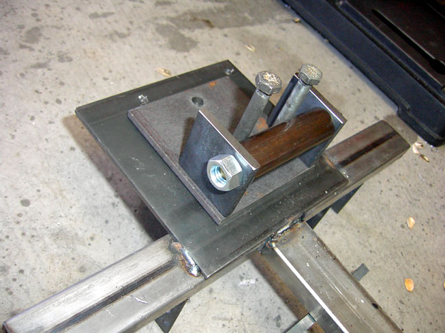 |
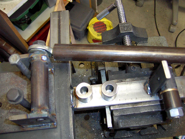
Here's the pivot tube on the jig. The base plate holes have been drilled and the height of the tube is exaclty the height of the pivot on the lever shock. |
 |
Going to use 2 heim joints on the inside pivot, but they will need to be spaced out from the mount just a bit so they don't hit during suspension travel. |
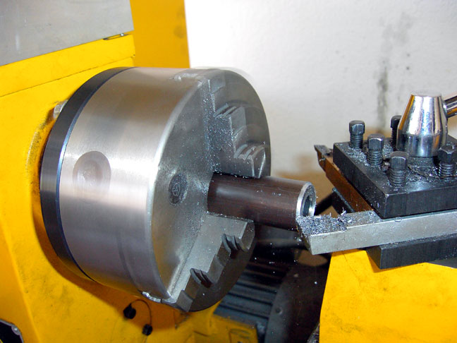 |
In order to get a good weld on the pivot tube, I turned a bevel on the ends (using a Lathe ) to allow good penetration of the weld. |
 |
This is the bevel on the tube, there's a similar bevel on the 1/4" thick pivot tube supports. |
 |
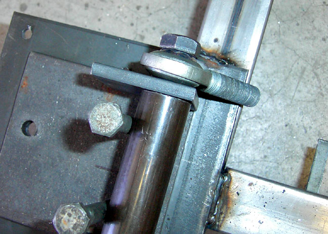
The pivot tube welded to the mount and a hiem joint with tube mocked up. |
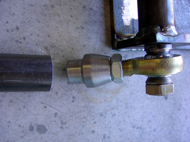 |
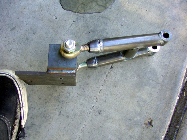
Look closely and you can see the beveled spacers on each side of the ball of the heim joint. These allow for movement without the joint hitting the welded end plate of the mount. Also visible is the threaded tube adapter to allow insertion of the heim joint into the 0.120" wall DOM tubing of the A-Arm. |
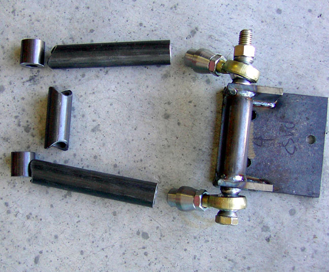 |
All the pieces layed out and ready for welding. The heim joints will allow for a bit of fine tuning of the front suspension, letting me use the stock geomtry or letting me dial in a bit of extra camber if I desire. |
 |
On the jig and fitted... |
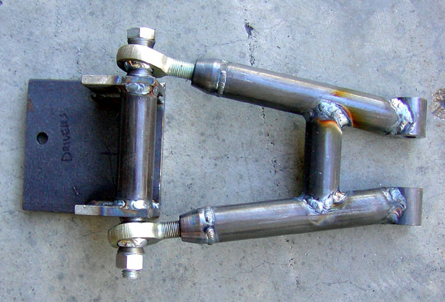 |
And the finished, welded, A-arm. |
 |
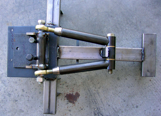
A side view of the A-arm and the mount. |
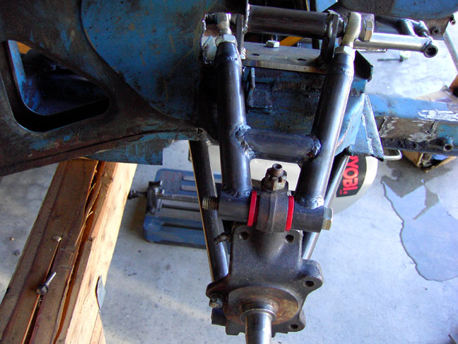 |
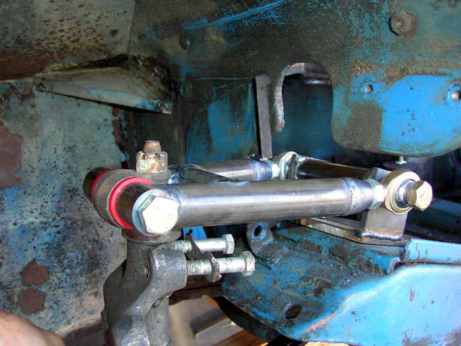
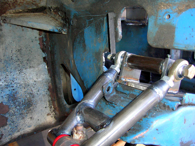
Installed on the car. The washers are left out for this picture. They will install on either side of the red urethane bushing on the trunnion and help with smooth, non-binding movement. |
 |
A small area had to be cut out of the inner fenderwell to allow the A-arm to fit. |
 |
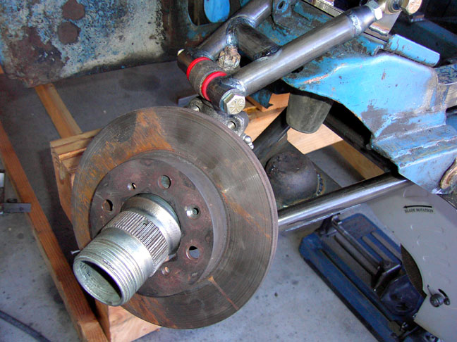
Full rebound... |
 |
View from the inside of the engine compartment. |
 |
Now, to figure out the Honda brakes, the sway bar and the tube shock conversion...... |