The Mite
Part 9
Front Suspension
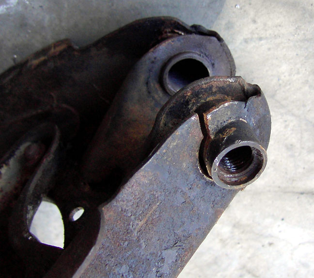 |
When I pulled off the front suspension a while ago, I just put the whole mess into a plastic crate in my shed. Now, cleaning off 35+ years of gunk, I found that the lower a-arm was cracked around the fulcrum pin mounts. What to do? I could find anothe pair of a-arms, replace the fulcrum pin mounts and fulcrum pin and hope that they won't develop any cracks in the future,.....or......I could make my own lower a-arms. |
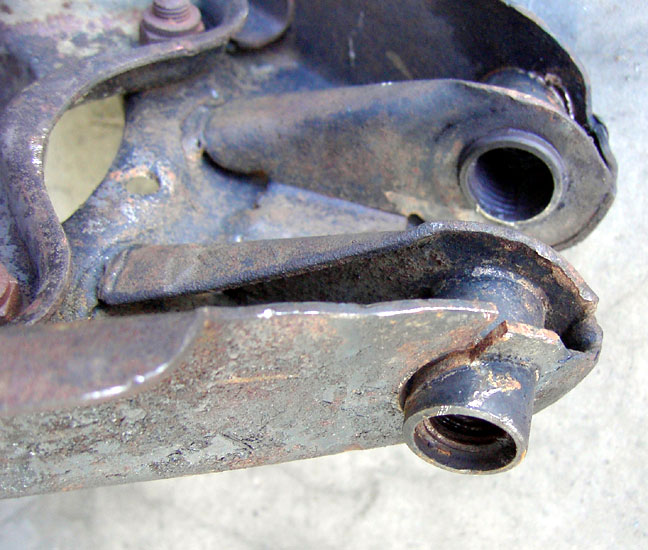 |
These arms are very light stamped steel and have no provisions for front anti-sway bars, nor do they offer a decent mounting location for a tube-shock conversion. (more on that later) |
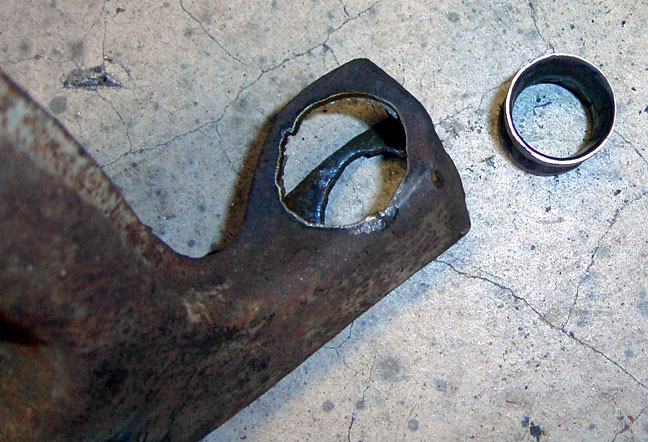 |
First order of business was to make a jig from the existing non-cracked a-arm. This way I could positively and accurately locate the inner pivot points and the fulcrum pin mounting points and the spring pan location. Then, since the inner pivot tubes on the a-arm are tapered in the center, I cut them out of the A-arms. |
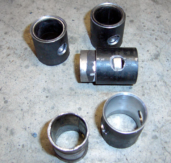 |
The tapered inner pivot tubes are pretty thin, and even though they would work in the stock a-arm, I decided to surround them with a thicker tube. Using thick walled DOM tubing, I turned the inside diameter to match the outside diameter of the inner pivot tubes, then drilled some holes in them to allow a plug weld to help secure them to the tubes. The tapered pivot tubes were pressed into the DOM tubing, then welded around each end and welded in the drill hole, then I faced both ends of the assembly to the proper length. |
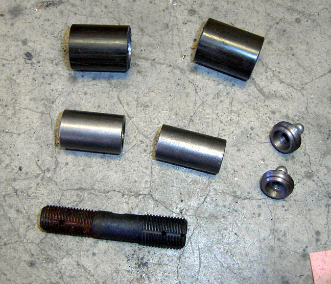 |
The fulcrum Pin mounts presented the same problem, so I took some 1" DOM tubing and turned the inside to the diameter of the fulcrum pin mounts. |
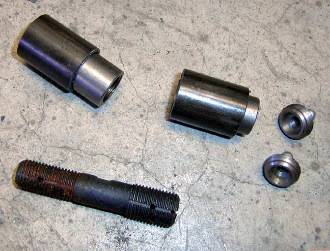 |
Then, using the same technique as above, I drilled holes in the DOM tubing to plug weld the fulcrum pin mounts to the DOM tubing to produce a strong, secure assembly |
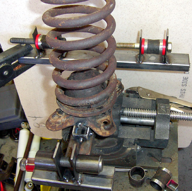 |
Here's the A-Arm jig in the vise. It is made of .120 wall rectangle tubing. |
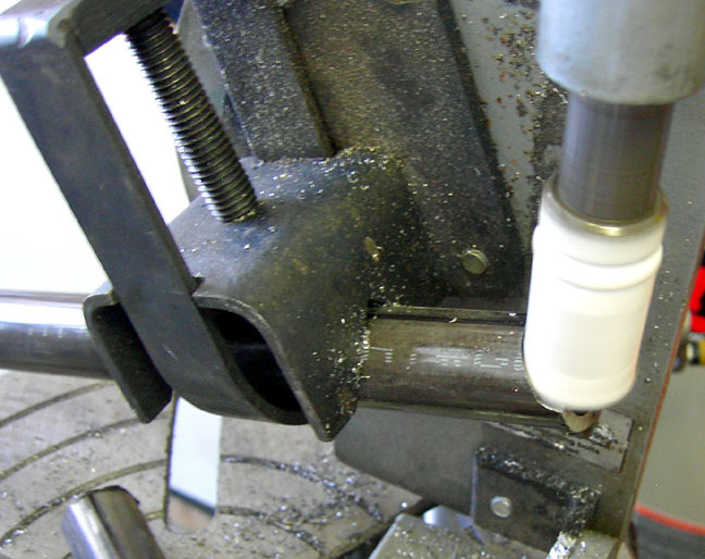 |
The Tubing Notcher |
 |
Mocking up the tubes in the jig... |
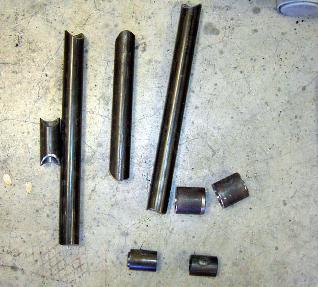 |
Here's the
collection of cut and beveled tubes that will make up 1 A-arm. I actually used a couple of books to learn about suspension geometry. Chassis Engineering |
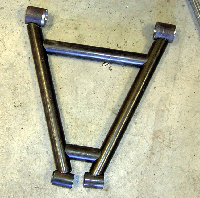 |
this is a mock up of the A-arm before welding. After this is welded together, I have to make a mount for the spring pan and then for the sway bar. I'll figure out a tube shock mounting point after I get the whole front suspension and brakes figured out. |
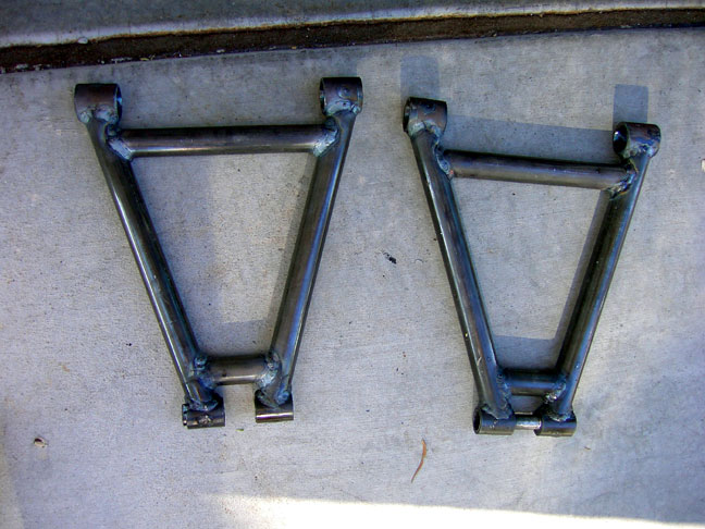 |
And
here they both are, welded and ready for the spring pan. I used a TIG welder to weld these together to be sure of good penetration and strong welds. I have a Miller TIG welder |
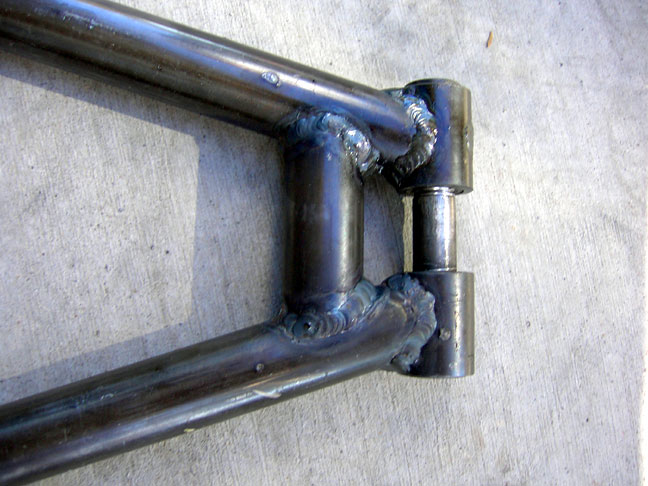 |
Close up of the tig welding on the cross brace. |
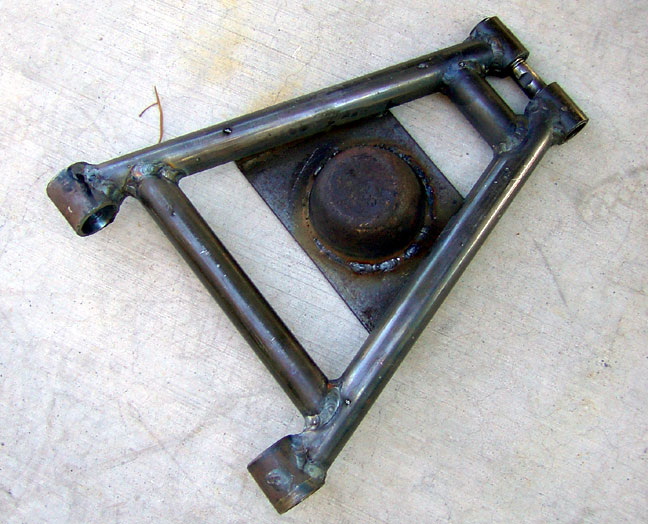 |
This is the completed arm with spring pan welded in. I used the top of the stock spring pan and cut a hole in the thick steel of the spring mount and welded it in. |
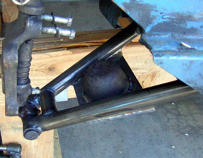 |
Here's
the arm on the car. Everything fits and moves correctly! Phase two will be making the new upper arms to get rid of the non-working, sloppy armstrong lever shocks. Stay tuned! |