
The Mite
Part: 33
Electromotive Crank Trigger and Valve Cover, oil pan and throttle body mods
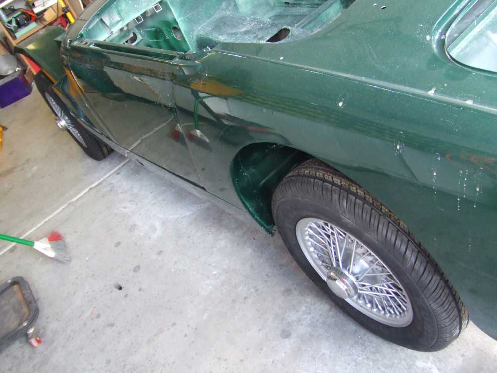 |
The back wheels are on the car and the car is resting on them. After I get the engine/tranny in the car and some weight on the back, I can measure the pinion angle and weld up the spring perches. |
 |
It looks pretty good, but the care sure sits high. I hope with a bit of weight and some time the springs will settle down a bit. Otherwise I'll have to put on some older ones. |
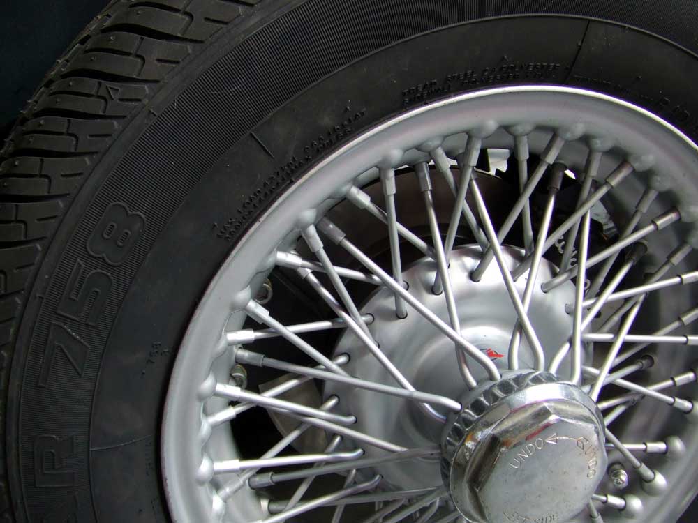 |
Here's the wilwood |
 |
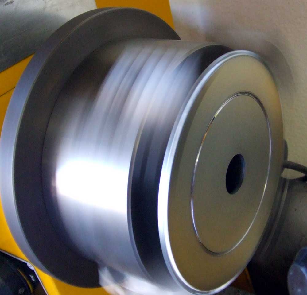
So, now I've got to begin prepping the engine for installation. The first thing is to get the magnetic pickup for the crank trigger figured out. As far as I can tell, nobody makes a bolt-on assembly for the trigger wheel on the 1.6 liter engines, so I have to fab one up myself. Here I'm turning the outer serpentine pulley off of the crank pulley-damper assembly. Once the outer pulley is removed, I'll have a spot to mount the trigger wheel. |
 |
The 60-minus-two tooth trigger wheel needs a bigger hole to fit on the pulley |
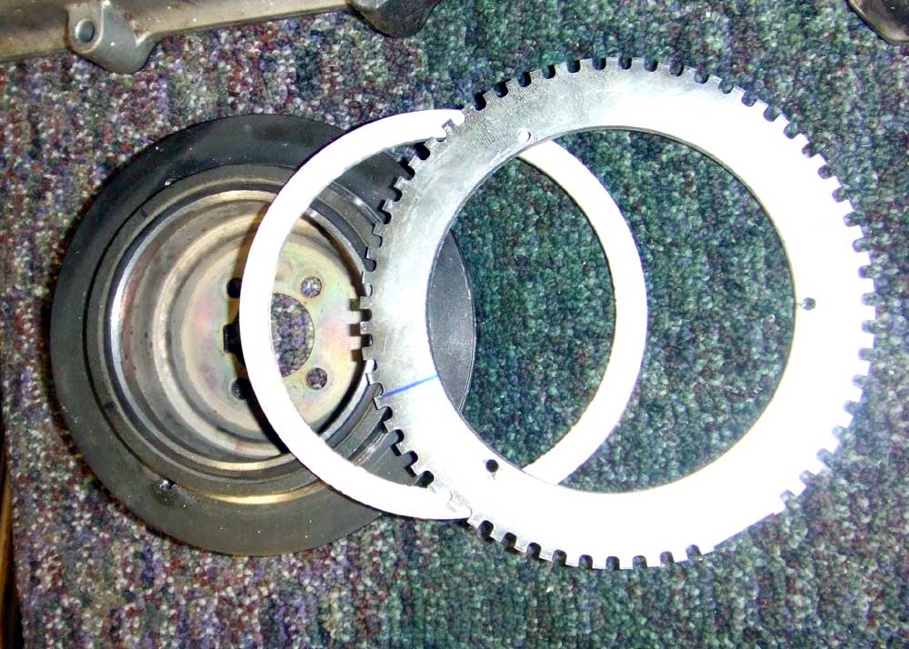 |
Here's the machined trigger wheel, a 1/4" aluminum spacer and the pulley. (if I was smarter, I'd have made the hole in the trigger wheel smaller and machined a step onto the pulley instead of having to make a spacer) |
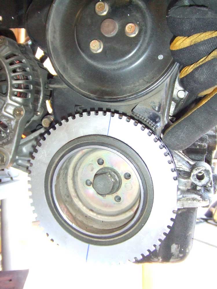 |
The trigger wheel assembly on the engine, with finger indicating where the magnetic pickup will go... |
 |
Here's the beginning of the bracket for the pickup |
 |
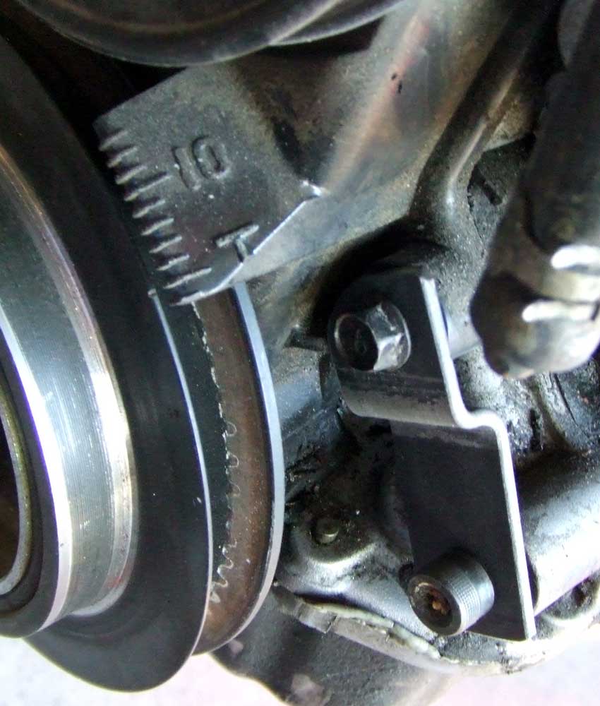
And with a little cutting and welding, the pickup bracket is complete |
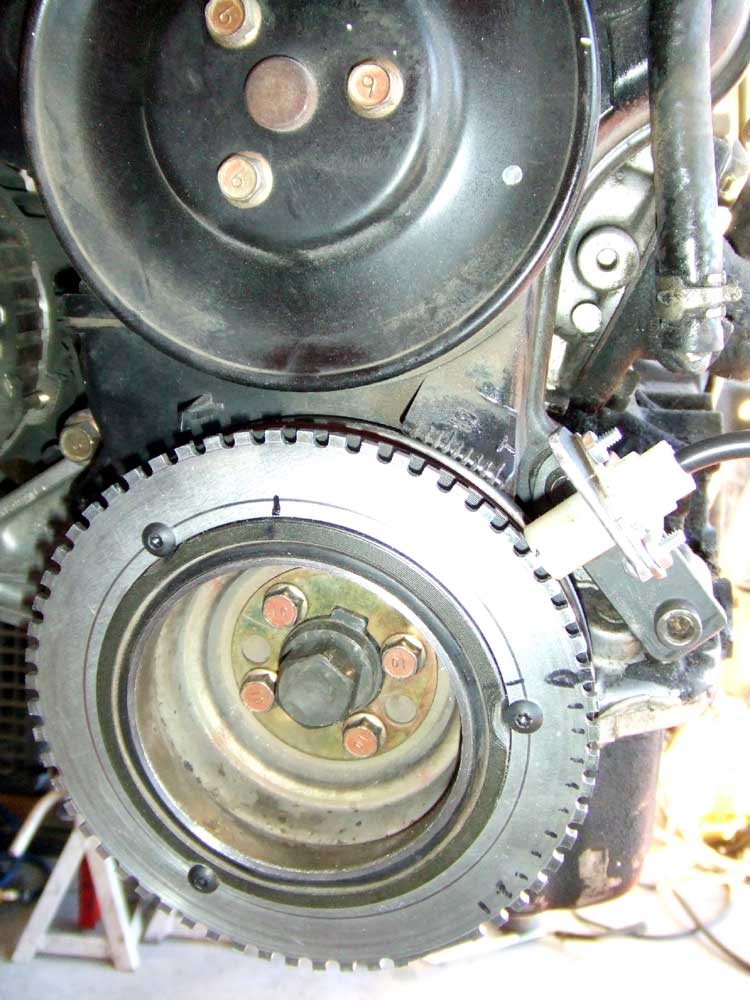 |
I drilled and tapped 3 holes in the pulley to correspond with 3 holes in the trigger wheel and spacer. They line up the trigger wheel in just the correct spot on the Magnetic pickup at TDC. |
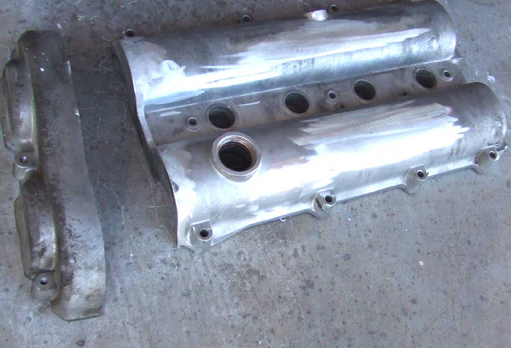 |
Now on to the valve cover. I did not want to have "MAZDA" staring at me everytime I opened the hood, so I TIG welded the letters full of aluminum and sanded them down. I also cut the pulley guard off because exposed cam gears and timing belts are cool. |
 |
See, exposed cam gears and timing belts are cool. Even on a 2.3 Ford. (238 RWHP on 12 lbs boost in a 1600 lb car...FUNN!) |
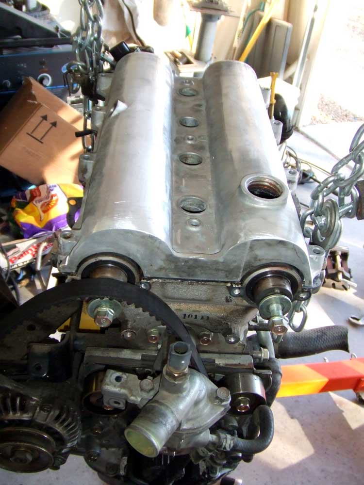 |
The Valve cover sitting on the engine. |
 |
The intake manifold needed some work, too. It had a bunch of emissions crap on it that needed to be removed. Here the one of the idle-air thingies was removed and a block off plate is in its place |
 |
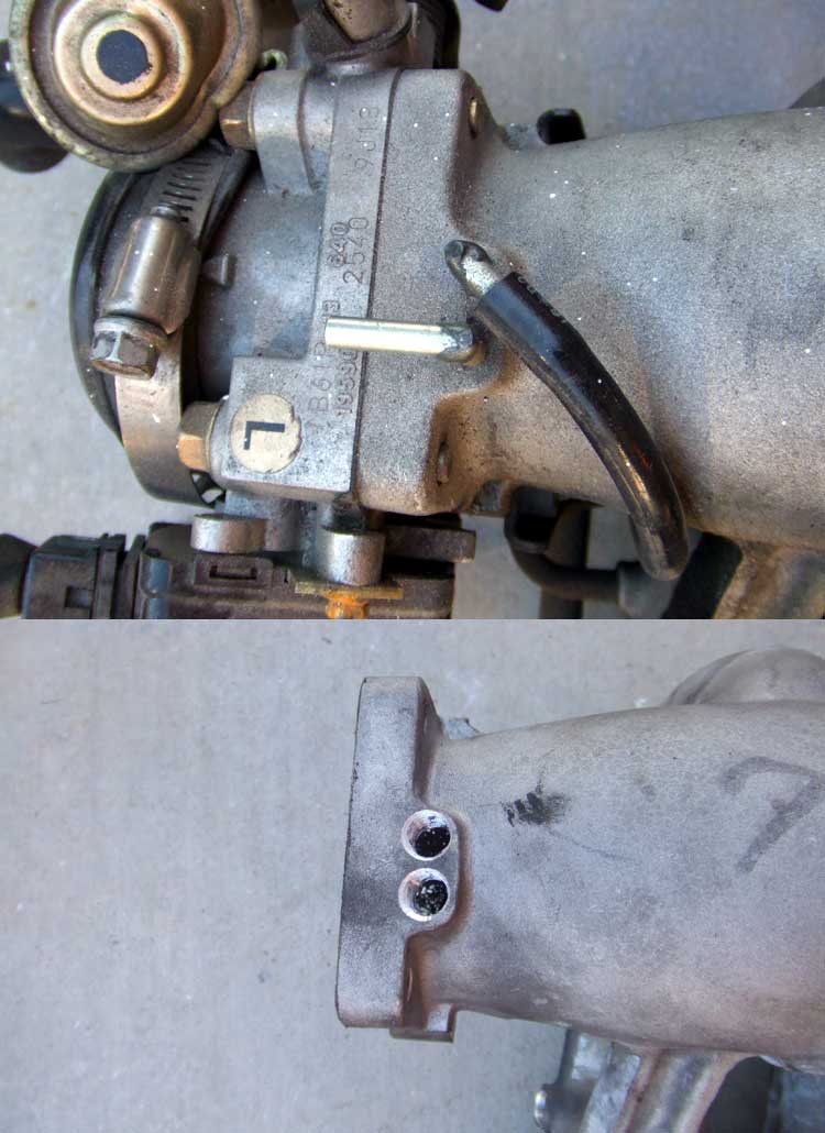
I will be using a GM style Idle air motor, so the Mazda one has to go. Top pic is the idle-air assembly on the throttle body, middle pic the assembly is removed, and the bottom pic is a semi-finished aluminum block-off plate |
 |
I wanted to get rid of all the goofy ports and hoses on the intake, so I grabbed them in the vice-grips, turned and pulled until they came out. Then I drilled and tapped all the holes with pipe threads so I can put in plugs |
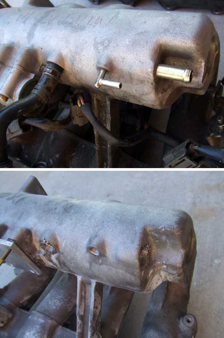 |
Here's some more of the ports removed. |
 |
I had to remove the pulley on the water pump to get the timing belt and cover off the engine. But...how to keep the pulley from spinning while I tried to loosen the bolts? Well, one of those stupid "as seen on TV" boa strap wrenches. |
 |
I shot the cam gears with a bit of black paint while they were off the engine |
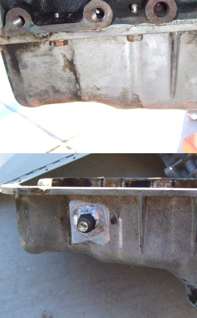 |
AND, I had to weld an A/N fitting to the oil pan for the turbo oil return. It was windy. |